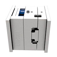
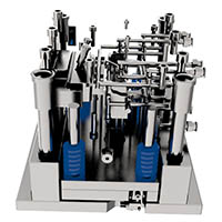
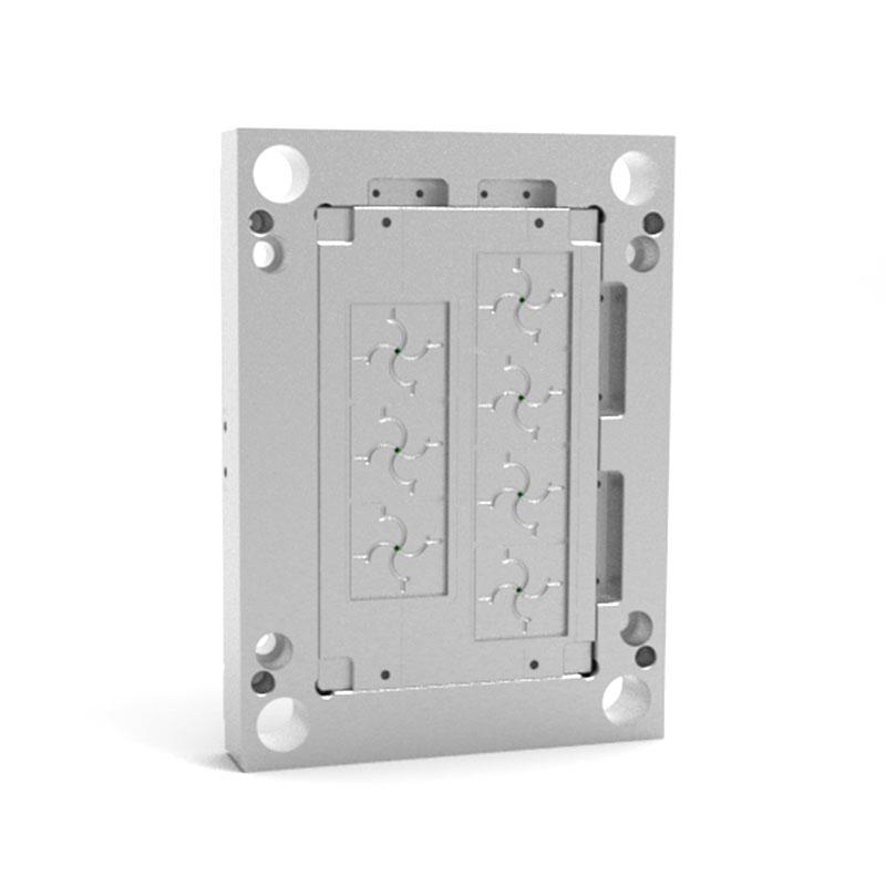
The general assembly drawing of plastic mold design shall include the following contents

A. Overall planning of plastic mould
① Some layout of plastic mold molding
② The layout method of plastic mold pouring system and exhaust system.
③ Parting surface and parting parts taking method.
④ Outline layout and orientation of all connecting parts, positioning and guiding parts.
⑤ Mark the height dimension of the cavity (not mandatory, as required) and the overall dimension of the mold.
⑥ Auxiliary things (take parts, remove mold things, correct things, etc.).
⑦ The serial numbers of all parts shall be numbered in order, and the detailed list shall be filled in.
⑧ Indicate skill needs and application clarifications.
B. Skill requirements for general assembly drawing of plastic mold:
① The functional requirements of some mold systems. For example, equipment requirements for ejection system and slider core pulling layout.
② Demand for mold equipment skills. For example, the bonding gap of the bonding surface of the rear parting surface of the mold equipment shall not be greater than the parallelism requirements of the upper and lower parts of the 0.05mm mold, and the scale determined by the equipment and the requirements for this scale are pointed out.
③ Mold application, assembly and disassembly methods.
④ Anti oxidation disposal, mold number, lettering, symbols, oil seal, storage and other requirements.
⑤ Requirements for mold test and inspection.

C. Make all parts drawings
The order of drawing parts from the general assembly drawing of the mold shall be as follows:
① First inside then outside, first messy then simple, first forming parts, then layout parts. Share painting, allow to expand or reduce. The view selection is reasonable, the projection is correct, and the installation is proper. In order to make the processing patent number easy to understand and convenient for the equipment, the graphics should be common with the general assembly drawing as much as possible, and the graphics should be clear.
② The marking scale needs to be consistent, concentrated, orderly and intact. The order of marking dimensions is as follows: first mark the dimensions of the primary parts and the die inclination, then mark the cooperative dimensions, and then mark all the dimensions. On the non primary part drawing, the cooperative dimensions shall be marked first, and then all dimensions shall be marked.
③ Surface roughness. Mark the most widely used roughness on the upper right corner of the drawing, such as “other 3.2”. Other roughness symbols are separately marked on each surface of the part.
④ Other contents, such as part title, die drawing number, material trademark, heat treatment and hardness requirements, appearance treatment, figure share, machining accuracy of self-measurement, skill description, etc., shall be filled in correctly.

D. The contents of self calibration of calibration, drawing review, drawing tracing and sun exposure are as follows:
① Whether the connection between the mold and its parts and the plastic part drawing, the raw materials, hardness, dimensional accuracy, layout, etc. of the mold and its parts meet the requirements of the plastic part drawing.
② In terms of plastic parts, whether the activity of plastic material flow, shrinkage cavity, weld line, crack, demoulding slope, etc. affect the application function, dimensional accuracy, appearance quality and other requirements of plastic parts. Whether there is a lack of drawing planning, whether the processing is simple, and whether the shortening rate of molding materials is correct.
③ In terms of molding equipment, whether the injection volume, injection pressure and clamping force are enough, whether the mold equipment, the South core and demoulding of plastic parts are in doubt, and whether the nozzle and mouth sleeve of the injection machine are correctly touched.
④ Mold layout
a. Whether the parting surface orientation and finish machining accuracy are satisfactory, whether there will be material overflow, and whether the plastic parts can be ensured to remain on the side of the mold with ejection equipment after mold opening.
b. Whether the demoulding method is correct, whether the size, orientation and quantity of the push rod and push tube are appropriate, whether the push plate will be stuck by the core, and whether the scratch formed parts will be formed.
c. Mold temperature conditioning. Power and quantity of heater; Whether the direction, size and quantity of the moving route of the cooling medium are appropriate.
d. For the treatment of the side concave of plastic parts, whether the structure of the side concave is appropriate, such as whether the slider and push rod in the core pulling organization of the inclined guide pillar disturb each other.
e. Whether the orientation and size of the pouring and exhaust system are appropriate.
f. Planning drawings
g. Whether the location of each mold part on the equipment drawing is appropriate, whether it is clear and whether it is missing
h. The part number, title, manufacturing quantity and internal manufacturing of parts on the part drawing are still outsourced, standard parts are still non-standard parts, the precision of parts’ cooperative disposal, the correction processing and allowance at the high-precision scale of molded plastic parts, and whether the material, heat treatment, surface treatment and surface finish Engineering degree of mold parts are symbols and clearly described.
⑤ Operation scale and cooperation scale of primary parts and formed parts. The scale number should be correct, and the manufacturer should not convert it.

⑥ Check the view orientation of all part drawings and general assembly drawings, whether the projection is correct, whether the drawing method conforms to the national drawing standard, and whether there is any missing dimension.
⑦ Check the processing function: (whether the layout, view drawing and scale mark of all parts are conducive to processing)
⑧ The primary operation scale of the recalculation auxiliary East and West professional correction shall be carried out in principle according to the self correction project of the planner; However, we should focus on the layout principle, skill function and operation safety. When tracing, first digest the graphics, describe according to the requirements of the national standard, and fill in all the scales and skill requirements. Self check and sign after tracing. The traced base map shall be submitted to the planner for correction and signature. The customary practice is that the relevant skilled personnel of the East and West production unit shall check, countersign and check the production skills, and then send it to the sun.
The general assembly drawing of plastic mold design
⑨ The preparation and production skill card is prepared for processing and production by the skilled personnel of the East-West production unit. In the manufacturing process of mold parts, inspection should be strengthened, and the key points of inspection should be placed on the scale accuracy. After the completion of mold assembly, the inspector shall check according to the mold inspection table. The first thing is to check whether the functional status of the mold parts is outstanding. Only in this way can we slang the manufacturing quality of the mold.plastic


I don’t think the title of your article matches the content lol. Just kidding, mainly because I had some doubts after reading the article.
Requesting a reward, your tipping is my motivation
https://paypal.me/molddl?country.x=C2&locale.x=zh_XC